
As a part of this University module, I am required to design and build an electronic instrument/interface. So, in this week’s blog, I’ll show you the first stage: Design.
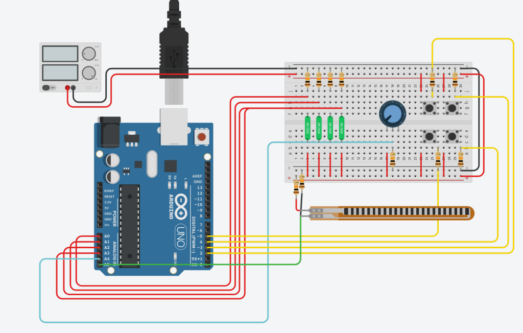
Looks a bit complex, doesn’t it? Don’t worry, I’ll break it down. Firstly, concentrate on the breadboard to the right; its where all the important stuff is. Those 4 green strips are slider potentiometers (Actually, they’re tilt sensors, TinkerCAD doesn’t have sliders, so these were the closest components that fit). They are going to be used to input values into an internal step-sequencer inside the Arduino, which will then be clocked at audio rate?
But how are we going to control the speed of that clock? Well, we have 3 methods. The first is using the push buttons shown to the right of the breadboard. These will allow for Octave and Semitone offsets, both up and down.
The second method is the strip underneath the breadboard is a touchstrip capacitor (again, TinkerCAD doesn’t have a touchstrip capacitor, so a flex sensor is the proxy for now). This is going to be used for pitch control, allowing for legato slides. I will consider making it so that your finger must be on the board for sound to be played, meaning we can play notes as well as drones.
The third pitch control method will be the rotary potentiometer in the center of the breadboard. This will allow the output of the synth to be mixed back into its pitch control, allowing for FM feedback.
Every control on the board is linked to ground through a resistor, with the Arduino reading its values before that. I think this is the correct way to do this; Of course, I will need to build the instrument, before testing the output values from each component at their extremes.
As a final point, I will list the flaws this instrument has:
- Aliasing. As far as I am aware, the Arduino’s internal clock does not go all the way beyond human hearing. Furthermore, there are no anti-aliasing measures. Take the feedback FM into account as well, and I can assure you this will sound messy. But I do like that.
- PWM as speaker output. Yes, you read that right. The only outputs the Arduino has are PWM, and I don’t have a DAC, nor the time to build one. This may be even worse that the above issue, as the maximum PWM speed on the Uno is 980Hz. Ouch.
Despite these issues, this is a proof of concept design, and is not expected to be perfect. Ideally, this would all be done using purely analog components, but I’m not that good at electronics.
Anyway, expect more blog posts that usual in the coming weeks, as I aim to document the progress of this instrument closely. Until then, cheerio!